

The accuracy class of a load cell always refers to its maximum capacity. The load cells cannot be over-dimensioned up to any extent, dependent on the required scale accuracy and the smallest portions to be measured, as the absolute measurement error is directly proportional to the maximum capacity.
The constructive outlay of a specially designed overload protection is always justifiable when the load cells need to be loaded up to their maximum capacity, where the risk of overload is always present. Overload protection should be provided to protect load cells in the following typical cases:
- The maximum loads of the load cells are not known.
- If strongly dynamic loads, e.g. falling product to be weighed (pulse loading), are to be expected.
Practice shows that load cells with smaller maximum capacities are often more frequently overloaded than load cells with high maximum capacity ranges. For example, a load cell with a maximum capacity of 20 kg can be significantly damaged simply by a falling wrench.
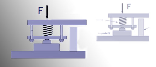
The designer can also realize and implement their own individual overload protection for a series of load cell geometries. Figure 1 shows a design proposal for an overload protection for the HBM load cell type Z6. The possible deflection/travel of the load cell is limited here by a mechanical stop.
The data sheet data nominal (rated) displacement describes the deformation value of the load cell at nominal (rated) loading. The possible travel, dependent on the load cell type and its maximum capacity range, is limited by a mechanical stop to 120 - 150% of the nominal (rated) displacement in order to prevent an overload of the load cell.
The stop is adjusted here with distance gauges. As the described deformations are very low - in practice just several 1/10 mm - fine thread screws that can be tensioned have been proven to be suitable. It is also recommended that the gap between load cell and stop is protected against contamination; because contamination can also be a cause for measurement errors such as unwanted travel limitation.
Displacement different to that specified in the data sheet may arise if the load cell support structure is soft. The overload protection frequently occurs too early because the mounting plate is bending. The gap between load cell and stop must therefore be increased. It is advantageous here for the user to be able to load the weighing device with the maximum capacity and then set the remaining gap to the mechanical stop from 0.05 to 0.1 mm.

Overload protection using the HBM load cell type Z6 as an example
Pretensioned spring packages:
Another form of overload protection is offered by pretensioned spring packages integrated in the force flow (Figure 2). If the maximum capacity exceeds a specific value, the spring is compressed and applies the force, via a suitable construction, to a mechanical stop.
The gap width is significantly wider with this form of overload protection. This makes the setting of the permissible loads simpler and more reliable. In addition, the spring properties crucially reduce the risk of load cell damage from pulse loading. Due to the low contamination sensitivity of these spring packages, the constructive and material outlay can be easily justified in a series of applications, compared to other forms of overload protection.

Overload protection of a type C2 load cell with a spring package
Transit protection devices:
It is recommended that suitable transit protection devices are provided for weighing technology systems to protect the load cell. Vibrations during transport can also lead to the described, partly extreme pulse loading of the load cells and therefore to their failure. Where possible, load cells should only be mounted at the final installation site of the system. In this case, a placeholder should be inserted in the system in place of the load cell. Dummies with the same external dimension of the load cell have been proven to be suitable. If this is not possible, thick sheet metal can also be used in this case as intentional force shunts.
Source Link
Other Articles from HBM - Hottinger Baldwin Messtechnik GmbH (Germany)
© HBM - Hottinger Baldwin Messtechnik GmbH (Germany) / International Weighing Review


Interested? Submit your enquiry using the form below:
Only available for registered users. Sign In to your account or register here.